When it comes to maintaining and troubleshooting the electrical systems of your ATV, understanding the wiring diagrams is crucial. This is particularly important for ATV owners who are looking to upgrade or modify their vehicle's components. In this article, we will be focusing on the 6-pin CDI wiring diagram for a 250cc ATV, providing a detailed guide for those who want to ensure their ATV runs smoothly and efficiently.
CDI stands for Capacitor Discharge Ignition, a crucial component in the ignition system of most ATVs. The CDI unit generates a high-voltage spark that ignites the fuel-air mixture in the engine. The 6-pin CDI wiring diagram is a specific configuration used in many ATV models, and understanding its layout is vital for troubleshooting and repair. In the following sections, we will break down the components and connections of this wiring diagram, providing a comprehensive guide for ATV enthusiasts and mechanics alike.
what is the importance of a 6-pin cdi wiring diagram for an atv 250cc
 The 6-pin CDI wiring diagram for an ATV 250cc is crucial for ensuring the proper functioning and maintenance of the vehicle's electrical system. It provides a detailed layout of the connections between the various components, including the CDI unit, spark plug, and ignition coil, which are essential for generating the high-voltage spark needed to ignite the fuel-air mixture in the engine. Understanding this wiring diagram is vital for troubleshooting and repair, as it allows mechanics and enthusiasts to identify and address any issues that may arise, such as faulty connections or damaged components. Additionally, having a comprehensive wiring diagram ensures that any modifications or upgrades to the ATV's electrical system are done correctly, ensuring optimal performance and safety.
where can i find a 6-pin cdi wiring diagram for an atv 250cc
 You can find a 6-pin CDI wiring diagram for an ATV 250cc on various online platforms, including blogs, forums, and e-commerce websites. Here are some specific sources where you can find the diagram:
Blog Post: The blog post titled "6-pin CDI wiring diagram for ATV 250cc" on Outcast The Ultimate Outdoor Wireless SPE provides a detailed guide to the wiring diagram.
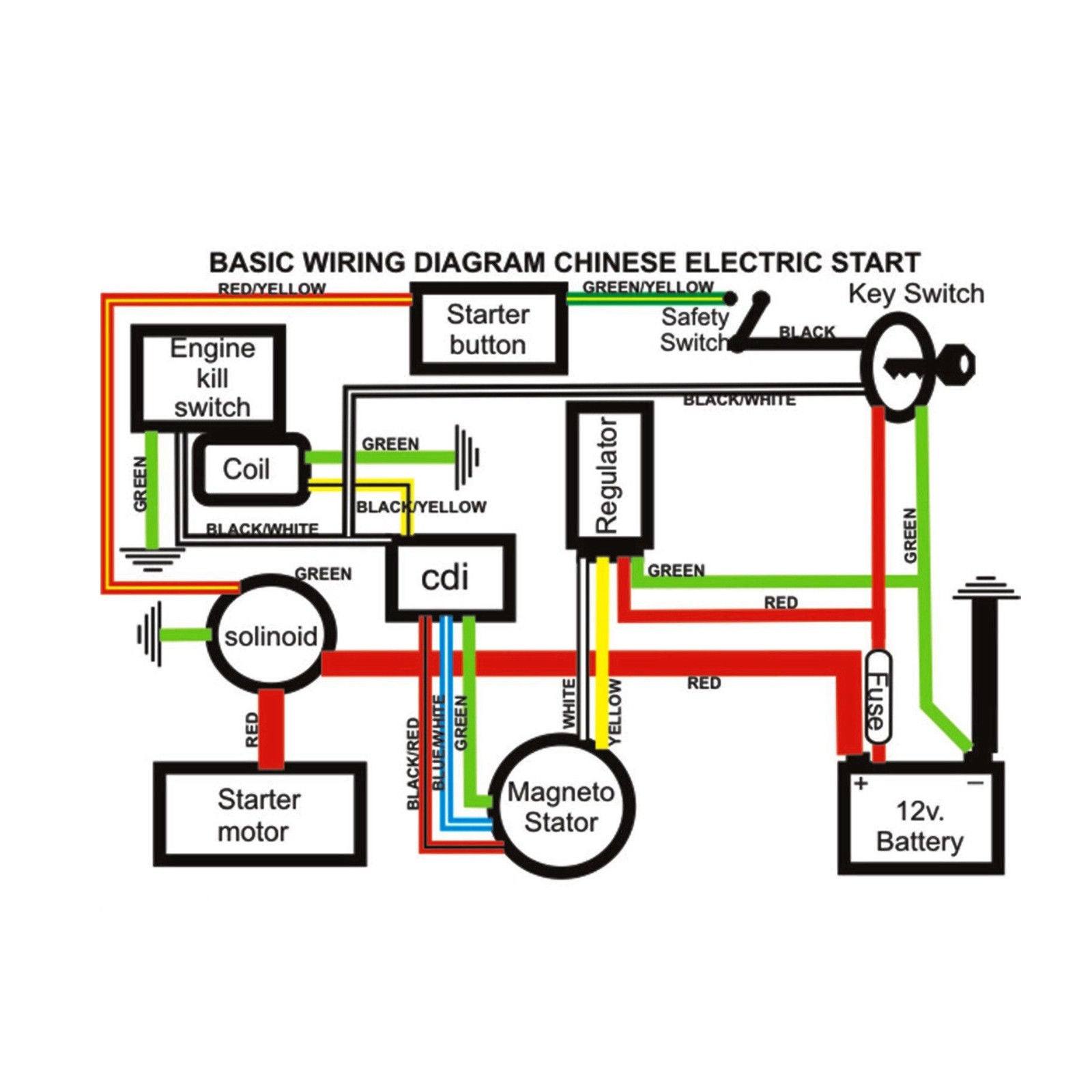
Chinese ATV Wiring Diagram: The Chinese ATV wiring diagram on Fabricante Shop offers a comprehensive layout of the electrical connections for 125cc, 250cc, and 300cc ATVs, including the 6-pin AC CDI wiring diagram.
ATV Connection Forum: The ATV Connection forum has a thread discussing the wiring of a 250cc ATV, which includes details on the 6-pin CDI wiring diagram. Although the thread is older, the information provided can still be useful for troubleshooting and repair.
Amazon Product Listings: Amazon offers various listings for 6-pin CDI boxes with wiring diagrams, specifically designed for 150cc, 200cc, and 250cc Roketa mopeds, scooters, and ATVs. These listings include detailed product descriptions and customer reviews.
These sources provide a range of information and resources to help you locate and understand the 6-pin CDI wiring diagram for your ATV 250cc.
You can find a 6-pin CDI wiring diagram for an ATV 250cc on various online platforms, including blogs, forums, and e-commerce websites. Here are some specific sources where you can find the diagram:
Blog Post: The blog post titled "6-pin CDI wiring diagram for ATV 250cc" on Outcast The Ultimate Outdoor Wireless SPE provides a detailed guide to the wiring diagram.
Chinese ATV Wiring Diagram: The Chinese ATV wiring diagram on Fabricante Shop offers a comprehensive layout of the electrical connections for 125cc, 250cc, and 300cc ATVs, including the 6-pin AC CDI wiring diagram.
ATV Connection Forum: The ATV Connection forum has a thread discussing the wiring of a 250cc ATV, which includes details on the 6-pin CDI wiring diagram. Although the thread is older, the information provided can still be useful for troubleshooting and repair.
Amazon Product Listings: Amazon offers various listings for 6-pin CDI boxes with wiring diagrams, specifically designed for 150cc, 200cc, and 250cc Roketa mopeds, scooters, and ATVs. These listings include detailed product descriptions and customer reviews.
These sources provide a range of information and resources to help you locate and understand the 6-pin CDI wiring diagram for your ATV 250cc.are there any tutorials or guides available for installing a 6-pin cdi wiring diagram on an atv 250cc
Yes, there are tutorials and guides available for installing a 6-pin CDI wiring diagram on an ATV 250cc. The search results provided include various online resources that offer detailed information and step-by-step instructions for troubleshooting and repairing ATV electrical systems, including the installation of 6-pin CDI wiring diagrams. For instance, the blog post on Outcast The Ultimate Outdoor Wireless SPE provides a detailed guide to the 6-pin CDI wiring diagram for a 250cc ATV. Additionally, the ATV Connection forum has a thread discussing the wiring of a 250cc ATV, which includes details on the 6-pin CDI wiring diagram. These resources can be useful for ATV enthusiasts and mechanics looking to understand and install the wiring diagram correctly. Moreover, online marketplaces like Amazon offer listings for 6-pin CDI boxes with wiring diagrams, specifically designed for 150cc, 200cc, and 250cc Roketa mopeds, scooters, and ATVs. These listings include detailed product descriptions and customer reviews that can help in the installation process. It is essential to note that the specific installation process may vary depending on the ATV model and the type of CDI unit used. Therefore, it is crucial to consult the manufacturer's instructions and any relevant documentation provided with the CDI unit or ATV to ensure a safe and proper installation. #EANF#As you have reached the end of this article on the 6-pin CDI wiring diagram for a 250cc ATV, we hope you have gained valuable insights into the importance of understanding the electrical system of your vehicle. The wiring diagram is a crucial component in ensuring the proper functioning of your ATV's ignition system, and it is essential to have a comprehensive guide to troubleshoot and repair any issues that may arise. We encourage you to bookmark this page for future reference and to share your experiences with others who may be facing similar challenges.
Remember that a well-maintained ATV is not only safer but also more enjoyable to ride. By understanding the intricacies of your ATV's electrical system, you can take proactive measures to prevent problems and ensure a smooth ride. If you have any further questions or concerns regarding the 6-pin CDI wiring diagram or any other ATV-related topics, please feel free to reach out to us. We are committed to providing you with the most accurate and up-to-date information available. Thank you for choosing Outcast The Ultimate Outdoor Wireless SPE, and we wish you a safe and enjoyable ATV riding experience.


No comments:
Post a Comment